I’m a believer. As a new guy I totally sucked at grinding lathe tools. It’s almost painful to admit how many stubby, misshapen, multi-faceted, overheated and just plain ugly lathe tools I made back then. The amazing thing is that some of those tools actually worked as well as the pre-ground tools that came with my lathe. I started to believe those guys that tell you, “… just get it close and it will work.” Of course, I was too embarrassed to call myself a hobby machinist with those Franken-tools so I bought an expensive set of inserted tip carbide tools that I thought would make a major difference but was disappointed. They couldn’t rough as deep or finish as well as my ugly high speed steel (HSS) tools, at least not on my lathe, so then I believed those guys that tell you, “… stick with HSS on a hobby lathe.” Hey, desperation can make you mighty receptive, you know.
Fast forward 15 years and now I believe, after having ground many experimental tools, that the best lathe tool for a hobby-class lathe is a HSS tool with its tip geometry modified to reduce the cutting forces it produces, ground on a belt sander.
Since standard tools are intended for use on industrial lathes their geometry can produce cutting forces that are excessive at times, especially when roughing but this can also affect sizing and finishing cuts. To be clear, cutting force is that force produced by the tip geometry of the tool that must be overcome to make a cut. We can look at it as a continuous resistance generated by the shape of the tool as it is pushed through the material during the cut. A standard HSS tool has a broad, wedge shape and creates a lot of resistance (carbide is even worse), so we must dial down our control inputs (depths of cut, feeds and speeds) to use them. If we alter the tool so it has a narrower included angle it cuts with less resistance, thus lowering the rigidity and power needed to make a given cut.
We still have to manage our control inputs but since the cutting forces are lower we would expect to be able to cut deeper, achieve better accuracy in sizing and finishing cuts, and finish better with greater ease before running into the rigidity and power limits of the lathe. And this is exactly what happens.
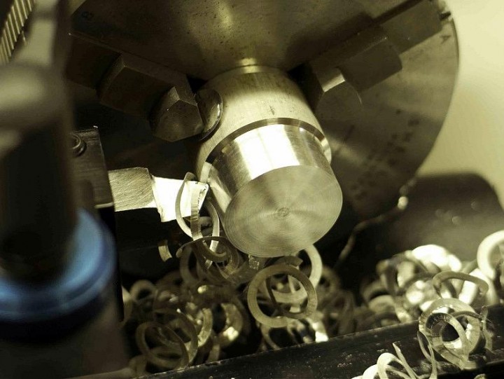
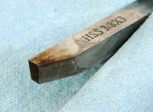
To demonstrate this I took a 0.050” deep cut in 12L14 mild steel on my admittedly older hobby-class manual mini-lathe using a very good quality inserted tip carbide roughing tool with a new insert, a sharp freshly ground high speed steel (HSS) roughing tool with standard tip geometry ground for steel, and the general purpose tool with modified tip geometry (not optimized for steel) that was ground for this discussion.
The carbide tool made the cut but chatter was excessive. Speed was as low as I could reasonably go and the feeding force was very high. The finish is really ugly due to all the chatter and the chips are tiny and powdery. Reducing the depth of cut to 0.010, the proper depth of cut for this insert, allowed it to cut as it should.
The HSS roughing tool did fair but there was a lot of chatter. Speeds and feeds had to be adjusted almost constantly to make it this far. Finish is rough but not excessive for a roughing cut. Chips are tightly curled due to the standard side rake. Reducing the cut to 0.030” allowed the tool to work much better.
The modified tool cut easily, speed was about 100 RPM higher than with the other tools and there was no chatter at all. Finish is much better compared to the other tools. The chips look more like loose shavings due to the sharper included angle at the tip.

Chips from the carbide tool, HSS rouging tool and the modified tool are distinctly different. You absolutely cannot fake a chip. They tell you exactly what is going on at the tip of the tool.
As you can see the modified tool performs favorably compared to the standard HSS and carbide tools, and I assure you they size and finish better as well. The trade off for this enhanced performance is a reduction in tip strength but most small lathes are not rigid or powerful enough to break a tip off, even with pretty aggressive cuts so it’s an acceptable trade off.
These modifications are not some deep dark secret. They are simply an alteration to the standard angles in ways that are already known to reduce cutting forces. You just need to know what to change, when and how to change it, and by how much. Grinding these changes into the tool then becomes very simple and will allow you to tailor the tool to your specific lathe and needs.
If this interests you then follow along as we go over basic tip geometry, at least enough to grind a tool with, and discuss how these modifications can be made. I’ll talk you through the thought process used to alter the tool we grind so you get a feel for what you’ll be doing in your shop. Then we’ll grind that tool on a belt sander, pretty much step-by-step, to solidify the concepts. We’ll finish off by showing you the Knife Tool, a facing tool I can highly recommend. Due to the length of this discussion I will break it up into three parts.
Please understand that tip geometry and cutting forces are extremely complex subjects. Entire books are written about this stuff by folks far more knowledgeable than me. I am not an expert on this subject; my goal is to give you only enough information to get you started and I consider this discussion to be a supplement to your reading. Therefore, any opinions, inaccuracies or errors are my own. The angle modifications I am sharing here were derived from experimentation in my shop and work for me and my lathe; your results willvary. These changes are NOT necessary; you can grind standard tools just as easily.
Finally, I am not a technical writer, engineer or pro machinist – just a guy like you – so I will write this in a style and language that I am comfortable with.
Experienced guy warning: Having been a new guy myself I recall the early grinding days well enough to know where the confusion points are. Accordingly, I am going to repeat and re-emphasize some points frequently, in several different ways, so that it clicks for the new guy. This will also be very detailed and necessarily longer because new guys need detail in order to succeed. For you more experienced guys, my apologies for the nausea this creates. Please ignore me and move on.
As always, working with machines and sharp stuff can result in injury or worse. Please be careful and proceed at your own risk.
First, the grinder
The bench grinder is the most commonly recommended tool for grinding lathe tools. This machine tends to cut slow, cut hot and cut facets. It may work in more experienced hands but for the new guy … maybe not the best tool to learn on.
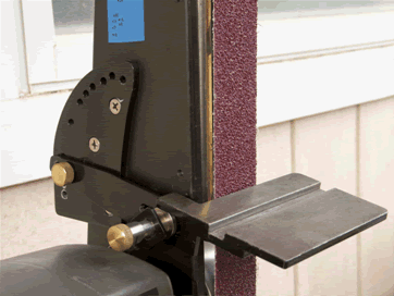
A far better option for grinding lathe tools is a simple belt sander, preferably one that uses 2” wide belts. These machines are cheap, widely available and surprisingly capable for home shop use. The smaller machines with 1” wide belts don’t have enough width to grind a tool evenly, the platen is too flexible, the belts wear too quickly, and coarser belts are harder to find.
As a tool grinder the belt sander is almost ideal:
- Belt sanders cut very fast and very cool when you use the right belt and a wax stick lubricant. Average grinding time for a 3/8” HSS tool is under 4 minutes and less than 2 minutes for a ¼” HSS tool.
- With their wide flat platens they allow for simple tool alignment so facets are easy to avoid. This is far, far, far better than trying to realign a tool to a narrow round wheel that requires frequent dressing.
- Belts are widely available, cheap, and do not require dressing, balancing, or conditioning. They also have a very good service life if used with wax lube.
- Changing grits takes seconds and going from shaping to a mirror finish by stepping up through the grits takes a few minutes. Honing to a final polish is less than a minute away.
- Belts will snap at the splice occasionally, especially if they are old. This will scare the crap out of you the first time it happens but I find that preferable to an exploding wheel. Know also that touching a finger to the edge of a running belt is very, very bad for you.
Most common belt sanders are not perfect in stock form. The OEM table is typically inadequate and needs to be upgraded to a solid table that can be quickly set to precise angles. The table should be made of steel to avoid sharp edges from catching and dragging as you move the tool across the belt.
The stock mild steel platen on these machines typically won’t last long with any serious grinding done on it. I suggest buying a ceramic glass liner you can epoxy onto a flat (preferably ground steel) platen to greatly resist wear from grinding operations. Better known as Pyroceram, these liners are readily available from knife making suppliers for about $20.00 as of this writing. The key thing is that the platen remains flat and does not flex at all. Once the table and platen are handled a belt sander makes a fine tool grinder and will also handle most other grinding jobs in the typical home shop.
Getting a handle on the angles
Take a look at this diagram from Machinery’s Handbook (MHB):
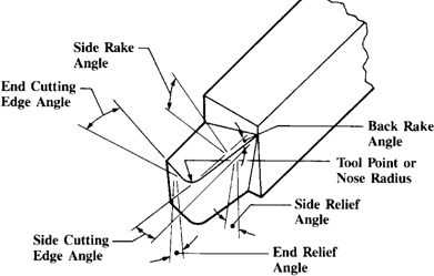
Fresh off the belt sander, all the angles in the diagram above have been ground into this roughing tool for steel. Despite the complexity of the diagram those angles are actually simple to grind, as you will see.
Lathe tools cut at a single point of contact so they are commonly called single point tools. This point is the interface between three surfaces – the side, the end and the top. Each of these surfaces is usually angled in two planes.
- The words relief angle in the diagram above refers only to the vertical angle of the side and end faces of the tool tip. The words rake angle refers only to the horizontal angles of the top surface of the tool. The words edge angle have to do with how the tool is shaped; due to the wide range of shapes a tool can take these edge angles are not found in the typical angle table.
- Relief angles are primarily clearance angles that allow the tool to cut at the tip and upper edges of the tool without the area immediately below rubbing against the work when the tip is set to center height. They are critical angles in that they form one half of the main cutting edge, the other half being the top rake angles. Relief angles affect finish, tool life, cutting forces and cutting temperatures. For a small lathe we want to use the largest relief angles we can get away with without weakening the tool. This is especially true with finishing tools where larger relief angles prevent rubbing and greatly improve finishes. Larger angles also enhance penetration of the tool into the work for all cuts, a good thing for a small lathe.
- Rake angles direct chips away from the working area of the tool. Note that there are two kinds of rake: side rake and back rake . Of the two, side rake is far more important for a turning tool, while back rake angles are less critical (except on parting tools where back rake assumes the importance of side rake on a turning tool). Different materials require different amounts of side rake for efficient chip clearance. In general, cutting forces will run perpendicular to the side cutting edge and as the tool cuts the chips will follow the path of least resistance. Rake, particularly side rake, provides this path. Much of the heat in a cutting operation is carried off by the chip so clearing those chips efficiently will reduce cutting temperatures. Being the other critical half of the cutting edge side rake, and to a lesser degree back rake, has much to do with reducing cutting forces. Cutting forces and cutting temperatures decrease, and tool life increases as side rake and back rake become more positive up to an optimal point (MHB). Therefore, for a given set of rake values in a cutting tool table you want to go for the higher value for use on a small lathe to improve chip clearance and reduce cutting forces.
- Edge angles define the tool’s shape as seen from the top of the tool. They vary with the purpose of the tool and also by how much strength is needed at the tip. Tools meant for heavy cuts, like a rougher, will have more mass at the tip to handle higher cutting loads, while a finishing tool will have a more delicate tip appropriate to the lighter cuts it is meant to take. These angles are less critical than the other parameters and are really dictated by your needs for tip strength, finishing potential and access to corners.
- The nose radius at the tip of the tool varies with the general purpose of the tool. Roughing tools will typically have a smaller nose radius, while finishing tools generally have a larger nose radius. Note that a large nose radius greatly increases cutting forces because it is constantly being pushed out of the cut. For tools up to 3/8” square it is best to limit the nose radius to a maximum of 1/64”. You can go up to a 1/32” radius on a finishing tool but lighter cuts are necessary. When forming or grinding it you do not need to measure the nose radius with a gage – just estimate it.
Honing a tool after it is ground is a controversial thing. Many experienced machinists say they don’t bother. However, any edge defects that occur during the grinding process will transfer to the work; we may not care too much about it for a rougher but for a finishing tool this is not a good thing. Since honing also extends tool life and reduces the need to re-grind a tool I can’t see a reason not to hone a tool.
Honing is best done with a fine or extra-fine diamond stone. I prefer the solid surface stones on a steel base, not the plastic base with dots. If I need to do a lot of stoning I use a 2” X 6” stone . If I am honing after grinding a tool on the belt sander then I use the credit card size; they are cheaper and easier to handle. I use the fine stone to get off most grind marks and the extra-fine to obtain a nice homogenous surface. Maintaining your tools after this will take only a few strokes per face.
Hold the stone in one hand and the tool in the other. Focus your pressure over the center of the face and stroke in one direction lightly, preferably under a running stream of water. Keep your wrists locked to avoid changing angles and creating facets. I suggest honing the side and end first, leaving the top of the tool for last; this removes any burrs and leaves a very clean edge. Your goal is to remove all evidence of grinding marks. Be sure to catch the nose radius when honing. If you need the finest finish possible for your work hone the tool, then polish it on a translucent Arkansas stone and your tool will cut like a razor.
Now that we have a better idea of what all those confusing angles are and what they do, we need to see how they are used to make a lathe tool.
Now we will look at the Angle Table, how we can modify the angles to reduce cutting forces, and we’ll discuss the different shapes lathe tools can take.
Using tip geometry
Here is a table that presents the table angles we need to set when we grind standard lathe tools. Note that the headings at the top of each column eliminate the word “angle” after each heading but otherwise matches the diagram above. The front relief (angle) in the table is the same as the end relief angle in the diagram above. The angles here are very important starting points for modifying tools. If you simply wish to grind standard tools then grind with the angles listed here.
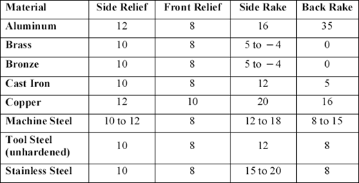
The values in the table are the number of degrees to which you must angle the grinder table for the particular feature you are grinding. For example, when grinding a tool for aluminum you will angle the table of your grinder to 12 degrees and then grind the side; doing so will create a side relief angle of 12 degrees (your table setting) and the side cutting edge angle (dictated by the angle you hold the tool at as you grind the side) at the same time. You then reset the table to 8 degrees and as you grind the end the table angle creates the 8 degree end relief angle as you shape the end cutting edge angle at the same time. You then reset the table to 16 degrees and as you hold the tool at a 35 degree angle (to the belt) you feed the tool straight into the grinder to cut the top face; doing so cuts the side rake at 16 degrees while creating the desired 35 degree back rake at the same time.
In order to alter the tip geometry of our tools to lower cutting forces: Use the largest angle listed in the table as a baseline, and then add about 25-40%. This works out to about 2-5 degrees higher than the largest recommended values and your tool will work better on your little lathe without endangering the tip excessively. While these changes may seem very small and insignificant the reduction in cutting forces they produce are anything but. The tool used for our cutting force demonstration earlier was ground with these conservative changes and it works well.
Keep in mind that none of the tip angles works in isolation.
- Increasing the relief angles without changing the side rake gives you a sharper interface at the edge so cutting forces decrease and finishes improve but you also limit chip clearance and lose some edge strength because the edge is not supported as well.
- Increasing side rake without altering the relief angles reduces cutting forces even more while improving chip clearance but finishing potential drops off a bit. Because the edge is better supported if relief angles are not altered increasing side rake does not sacrifice edge strength as much.
- The effect of increasing back rake is not nearly as noticeable as when altering side rake. However, increasing back rake will tend to focus the cutting forces at the tip of the tool while helping side rake to flow the chip out of the cut.
- If you increase both the relief and side rake angles then cutting forces plummet but the tip and edge strength is reduced a lot more so be aware of it when the tool will experience high cutting loads. This is less of a concern for finishing tools.
- The shape of the tool has a significant impact on strength. The more mass you have in the tip the more latitude you have with angle changes.
Table Notes:
- Side rake for brass and bronze is not zero in the table but a flat, un-ground top works well for these materials. Profiling tools also have zero top rake. A flat rake keeps the tool from digging into soft, grabby materials or when there is a lot of edge contact between the tool and the work. You don’t have to grind the top but you should hone it.
- Side rake is the angle that varies the most with different materials. In fact, side rake is the key variable at that tip. If you look at the relief angles in the table you will see that they don’t vary much between materials because clearance on a round part is still clearance and once you have it then, well, you have it. When you vary the side rake the included angle of the side and end suddenly becomes more, or less, acute. It is this alteration in included angle, also known as the angle of keenness, which changes to accommodate various materials. Seemingly small changes to side rake can have a major effect on cutting forces and how the tool cuts. Pay attention to side rake and use it to your advantage – it’s a major player.
- Side rake for Stainless and Back Rake for Aluminum are very aggressive. That’s a lot of steel to grind off. You may want to look into grinding chipbreakers when grinding tools for these specific materials. Chipbreakers break the long, stringy and dangerous chips into smaller pieces and are much easier to grind than the whole top of the tool. I won’t go into chipbreakers here but you should know about them.
For optimum performance you can grind a set of tools (rougher, facing and finishing) for each material you commonly work with. They will work far better than general purpose tools and are worth the time it takes to make them. If you grind them as you need them you will have a complete collection in no time. If you do make sets I suggest grinding the same face of each tool before changing your table angle to save setup time.
On the other hand, you can actually get away with less than optimal geometry. For example, you can grind a general purpose tool that will work on mild steel, aluminum, stainless steel, plastics, tool steels, semi-hardened steels and brass. The tool we will grind as an example below is one of these general purpose tools and the tool angles used are typical for a tool that has to cut multiple materials under varying conditions. These tool angles are a compromise, just as the shape of a general purpose tool is a compromise but they work fairly well.
General purpose tools allow you to minimize the number of tools you need to grind. For example, if you had to minimize the number of tools in the drawer you could have a general purpose right hand and left hand tool, a RH and LH general purpose knife tool for facing (see the end of this discussion), a zero-rake 60 degree threading tool and a zero-rake round nose tool with a 1/64”-1/32” nose radius (for between-shoulders work and general cutting of brass). Add a HSS blade-type cut off tool with a 7 degree face used in a rear-mounted tool holder and you can handle most general jobs in a hobby shop.
An important angle you may see that isn’t in any table is called the Lead Angle (LA).
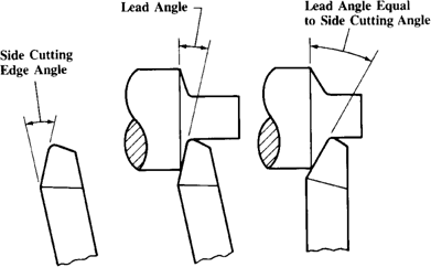
The LA is not ground into the tool; it is set by positioning the side cutting edge relative to the work piece. In general, a tool is used with the shank positioned perpendicular to the work; in this case, the LA is equal to the side cutting edge angle. However, increasing or decreasing the LA of the tool to suit your purpose works better.
Increasing LA can significantly improve finishes; for this reason MHB recommends using the maximum LA possible as long as there is no chatter. Remember that increasing LA also increases cutting forces because more of the side cutting edge comes into contact with the work. The effect of this is most readily seen on thin, flexible work pieces in the form of chatter. On larger pieces that don’t flex much a large LA can really improve finishes.
If you develop chatter at any time, especially on thin pieces or on hard materials try reducing the LA (move the side cutting edge more perpendicular to the work) and things will improve. In some cases going to a negative LA really helps, especially on thin work or an ambitious roughing cut. The effect of reducing LA is equivalent to reducing depth of cut and increasing feed, which has a positive effect on reducing chatter. Try playing with LA to further modulate cutting forces on the lathe – it can be useful.
Another term you may see is the Angle of Keenness. This is the included angle formed by the side and top of the tool as you look at it from the tip end of the tool. For harder materials this angle is less acute and for softer materials it is more acute. Back in the day, before angle tables became widespread, machinists ground their tools with this angle: less acute for hard stuff, more acute for soft stuff. Since the hardness of the material being cut is accounted for by the angles found in the angle table I ignore this angle but mention it here for completeness. If you were paying attention, this is the angle that changes as you alter your relief and side rake angles. Those old guys knew what they were doing.
Lathe tools come in many shapes, each suited to a particular task.
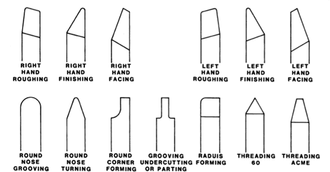
The top row shows the three basic turning tool shapes in both right hand (cuts toward the chuck) and left hand (cuts toward the tailstock) versions. All are used at normal turning speeds. These tools are typically used with their shanks perpendicular to the work but you should change their lead angles to suit the situation. These shapes have proven themselves over time to work very well but you are not limited to them in any way. For example, a “general purpose” tool could look like the facing tool but since we may have altered our relief and rake angles for our tool we may want more strength in the tip. In that case we could grind something that is halfway between a roughing and facing tool and it would work for most operations. That is the shape we will grind later.
When we shape a tool we are grinding the Side Cutting Edge Angle (SCEA) and End Cutting Edge Angle (ECEA) to give us the shape we want. Again, these angles are determined by the angle at which you hold the tool blank at as you move it across the grinding belt. Unless you need a specific shape, jigs are not necessary to grind them – save your money and do it by hand.
General things to note:
- Rougher: It has greater mass at the tip to handle the cutting forces encountered with deeper cuts. It is shaped, and used, with a shallower lead angle that allows a deeper cut with less chance of chattering. The nose radius is smaller than that of a finisher; 1/64” works. It cannot cut into a square corner. The strongest of turning tools, it allows the greatest latitude for modifying your relief and side rake angles. For interrupted cuts when the cutting edge is pounded hard keep your relief angles at baseline to add strength.
- Finisher: This has a delicate tip and a more generous nose radius of up to 1/32”. The rounded tip creates greater cutting forces so it is meant for lighter cuts. It cannot cut into a square corner. It is the weakest of shapes but meant for light cuts so higher relief and back rake angles work well with this tool.
- Facing: Note that the angle between the side and end cutting edges is less than 90 degrees. This allows the tool to cut into a corner, which is a facing operation. The nose radius can be ground smaller than 1/64” to cut a cleaner corner. Most of the cutting action is done at the side cutting edge (higher cutting forces) so lighter cuts are needed. Here, you can boost side rake and keep relief angles more conservative (25-30% range) to preserve edge strength.
- The tools in the lower row are profiling or forming tools. All of these tools have a potentially large contact area so cutting forces arevery high; they are therefore meant to be used with shallower depths of cut and much lower speeds. All except the corner forming tool can be ground on a belt sander; this tool is the only one I would use a bench grinder for if I needed one. All of these profiling or form tools typically have zero top rake but their relief angles are the same as a turning tool.
Regarding the 60 degree threading tool:
- Use a 60 degree template or “fishtail” to grind this accurately or your thread form will suck. Starrett sells a good one for low cost. Basically, you grind the sides to match the notch in the tool until you get an exact match. Don’t settle for close – get it dead on.
- Grind the side relief angles on both sides of the nose at about 15 degrees for efficient cutting on a small lathe. 15 degrees is enough to cut freely but not aggressive enough to sacrifice edge strength. Cutting loads are very high when threading so try not to exceed this 15 degree recommendation if you can help it.
- Grind a very small flat (just visible) at the tip to keep it from cracking off.
- The top has zero rake. If you use the set-over method for threading you can get away with a small amount (5 degrees or so) of positive side rake. Be sure to hone this tool before using it.
- For a parting tool I highly recommend you use a blade-type or T-type tool made of HSS and grind a 7 degree (standard angle is 5 degrees) relief angle under its tip. Best results come from using a rear mounted tool holder to increase rigidity in your setup and using the right blade thickness for the diameter and material you are cutting. You can also grind a parting tool from a square blank if you like but its tricky and a lot of work.
Grinding a tool
ALWAYS wear eye protection, hearing protection, a dust mask and leather gloves when grinding. No tool is worth sacrificing your body parts.
Remember, no angle works in isolation
Think about what you need with regard to shape, strength, tip access, and the type of material(s) you will use the tool on. Choose your relief and side rake angles and when you are clear on what you intend … just grind it that way. This thought process is illustrated below.
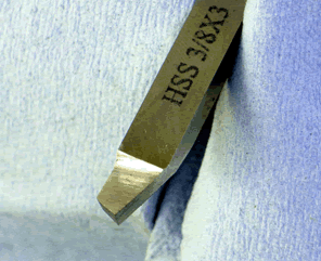
Let’s grind a general purpose right hand tool from a 3/8” HSS blank that should work with steel, aluminum, plastics and stainless. It is not optimized for any of these materials but should work fairly well with all of them. You can rough, face and finish by varying the lead angle of the tool. By choosing a general shape for multiple materials we need to think about the compromises these choices force on us:
- The overall shape will be half-way between a rougher and a facing tool. To allow this tool to face into a shoulder we’ll give it an end cutting edge angle of 80- 85 degrees. This more acute angle reduces tip strength a little but is of no concern on a small lathe even when roughing, though it does add to the equation.
- To reduce cutting forces we will use a conservative side relief angle of 15 degrees and a more aggressive end relief angle of 15 degrees; both changes will improve facing, finishing and edge penetration. In addition to turning you can also use this tool for chamfering with the side and end.
- Since I am losing some strength by using greater angles for side and end relief as well as from that more acute end cutting edge angle, I’ll try to conserve some strength and compromise chip clearance a little by keeping the side rake conservative at 15 degrees. Back rake is at the high end of the standard range at 15 degrees to further assist the side rake in improving chip clearance; it also boosts finishing potential.
- We’ll use a nose radius between 1/64” and 1/32” to allow a deep cut while still giving a fair finish.
- A LH tool is the same except the shape is reversed.
As you can see, multi-purpose tools require some compromise. I have given more emphasis to tip strength because we will also be using this tool for roughing, which creates large cutting loads in harder materials. We’ll discuss this further in the End Notes.
General Advice:
- If you are new at this I suggest practicing on mild steel key stock from the hardware store, not HSS. It grinds easily and is cheap. Just cut it to the same size as your HSS blanks so you get a feel for handling a bit.
- Let the belt cut; you want to use only moderate pressure – enough to keep the belt cutting continuously – and keep the tool moving back and forth across the entire width of the belt. The steel will show you some color to indicate how hot it is getting. HSS can get into the low red range without compromising the steel but if I see anything beyond dark straw I know I am using the wrong grit, my belt is worn or I’m putting too much pressure on the tool when grinding. It the tool gets too hot to hold let it air cool or just set it down on a brick – it cools fast.
- The usual sequence I follow when grinding a tool is to cut the side first, then the end, followed by the top. This isn’t written in stone. You can grind the top face first to ensure the top and side cutting edges meet exactly at the edge as they should – think about it.
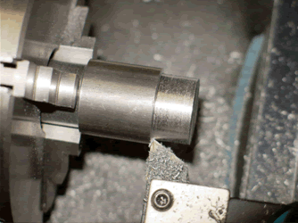
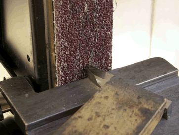
Seen below is my grinding setup. It is a ½ HP Craftsman 2” X 42” belt sander with a custom steel table settable to precise angles. The platen is a 2”W X 9” L X 1/4” thick piece of O-1 ground steel to which a Pyroceram liner is epoxied; it is dead flat after years of frequent hard use. It is equipped with a 24 grit Aluminum Oxide belt, soon to be coated with a wax stick lubricant. This belt cuts very fast and very cool when using only light to moderate pressure applied toward the belt and I highly recommend it for shaping. Just ease up on the pressure as you near the end of the grind to eliminate coarse grind marks. After shaping, you can change to progressively finer grits and produce a near mirror finish if you choose.
The table is set to 15 degrees to cut the side relief angle, the vertical angle under the side edge. The side cutting edge angle is determined by the angle with which you present the tool to the belt; as you grind it you are grinding the side relief angle at the same time. For this tool the side cutting edge angle is approximated so that 60% of the side is ground off when I am done. If I want a rougher I grind 40% off the side, 70% for a facer and 80% for a finisher.
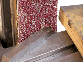
The block of wood in the picture above backs the tool while grinding; one hand holds the block to maintain moderate pressure into the belt as the tool is moved side to side across the belt with the other hand. Be sure to relax your hands and sight along the top of the tool where it meets the belt; keep that edge parallel to the belt to help you maintain your cutting angle and prevent facets from forming. Don’t rush the grind – take your time and work safely.
Note the dark straw discoloration after grinding the side; this is about 490 degrees, which is less than half of the way to barely red hot. The tool cut readily in about 2 minutes and cooled after grinding this face in about a minute. (I suggest re-applying wax before each face is ground.)
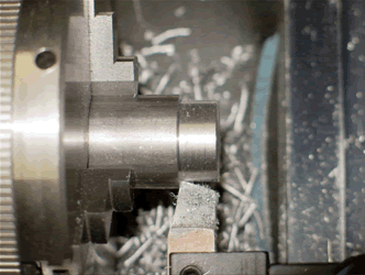
Next we cut the end cutting edge angle. I am using the same 15 degree table angle so the end relief angle, the vertical angle of the tool under the end edge, will be 15 degrees. I am presenting the tool to give me an 80-85 degree end cutting edge angle relative to the side cutting edge angle. For this cut the block is used to move the tool side-to-side while my other hand applies pressure into the belt. When grinding, keep the block close to the tip for best support.
Again, note the dark straw color indicating the tool is cutting very easily without a lot of heat. This cut took about 10 seconds.
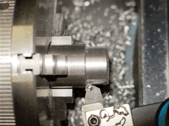
The last face we need to cut is the top. I have added an auxiliary table to provide support for the tool on the right side of the belt. The belt is tracked to the right so it overhangs the platen about 1/16”; this is to prevent cutting the belt and creates a smooth fillet in the back rake as we cut into the steel. The table angle is still at 15 degrees.
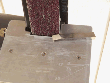
Below the tool in the picture above you can see some scribe lines on the right side of the table with different angles; these angles help me set the back rake. I align the tool to the 15 degree line and bring the tool to the belt without changing the angle. As the tool is fed straight into the belt it will begin cutting the side of the tool closest to the table. As the cut progresses it cuts closer and closer to the side cutting edge, which is presently on top of the tool; I stop just as the cut reaches the top edge. The result is a 15 degree side rakeand a 15 degree back rake.
Remember to use the wood block to apply steady but only moderate pressure so the belt cuts continuously, while controlling/maintaining the back rake angle with the other hand. It’s easier than it looks – just a straight push into the belt. When done correctly the tip of the tool will be at the same height as the shank of the tool.
The above photo shows the finished top surface. I checked the progress of the cut 4 times. When resuming grinding just align the top edge of the tool so it is parallel to the belt and you won’t produce facets. Grinding time for the top was about 90 seconds so total grinding time for the entire tool is under 4 minutes. This is typical. Cobalt tools usually take a minute longer, while a ¼” square tool takes 2 minutes less.
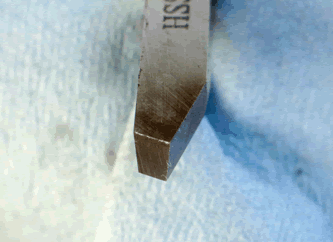
If you add a nose radius you can use the tool as it is. If you hone it with a diamond or Arkansas stone it will cut better and last longer. I usually cut the nose radius manually with a diamond stone rather than use the belt. I find I can control the radius better this way. If you choose to grind the radius use a fine grit belt and angle the table to match the angle at the tip of the tool. Blend the radius smoothly with the side and end faces.
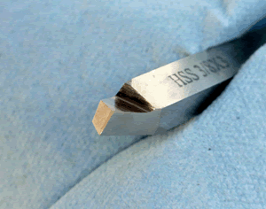
Here the nose radius has been formed and the tool has been honed briefly with a diamond stone. The flat tool faces make it easy to hone the tool quickly.
Now, let’s see if this tool will cut:
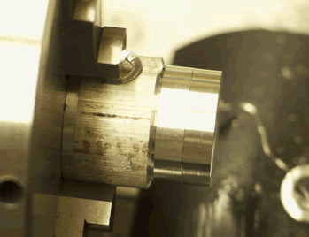
A 0.050” cut in 6061-T6 Aluminum. I then increased the lead angle and made a 0.005” deep pass halfway in to show the finish produced solely by a lead angle change. The tool works well in aluminum, with decent chip clearance.
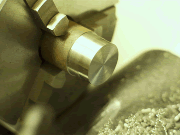
A 0.025” pass in 12L14 steel. Again, a finish pass was made halfway with an increased lead angle to a depth of 0.005”. Note that the tool faces well. This cut in steel was effortless for the lathe, with little resistance when feeding and excellent chip clearance. We know that we can easily double the depth of cut
Here is another angle to show how the tool cut these different materials and the effect the lead angle has on the finish. Cutting speed was the same between roughing and finishing. A bit more lead angle, speed and some cutting fluid would give us a mirror finish. By the way, these finishing cuts are very accurate.
End Notes:
Our general purpose tool works reasonably well, at least in mild steel and aluminum. It would work even better if the angles were optimized for each material but even with the compromises we made it is certainly better than standard geometry tooling on a hobby-class lathe. I hope this point is made well enough to convince the new guy that learning to grind a tool is a skill worthy of his time.
I would encourage you to experiment with your angle changes until you find what works best for your lathe. The 25-40% modification range is conservative but works well for me. You will need to find what works for you. When experimenting I suggest using cheap import blanks and keep careful notes on what you did and how it worked. When you are happy with your results then grind a good tool from a blank you trust. Keep your notes so you can refer to them to either regrind the tool or reproduce it. I also suggest grinding material-specific tools instead of general purpose tools; they work so much better and require far fewer compromises.
With that said, I have found the following to work well in my shop:
- For all roughing tools and tools meant for most steels, it is better to keep relief angles conservative, from baseline to 25% above baseline, and boost side rake into the 30-40% range. This reduces cutting forces but preserves edge and tip strength because the edge is better supported. Side rake above 40% does not seem to provide greater advantage for steel; in fact, edge life falls off so cutting forces may increase.
- For finishing tools I tend to go 30-40% above baseline on relief angles because this really helps the finish. I keep side rake down in the 25-30% range to keep strength reasonable. I use a nose radius just a bit bigger than 1/64”; this is enough for a mirror finish on most materials. I also increase back rake for finishers into the 30% range – this focuses the cutting forces at the very tip, which is okay since finishers are used with very shallow cuts.
- The only facing tools I use are Knife tools, described below. I have one for hard stuff and one for softer stuff and they work superbly. Keep relief and back rake angles in the baseline-25% range but boost side rake into the 25-40% range. Since facing tools cut with the side edge we need more strength at the edge and conservative relief angles do this.
- Brass likes an increased relief angle in the 30-40% range. Hone your brass tools and keep them very sharp.
- Delrin likes 30-40% relief angles and a large side rake (in the 40-50% range) to increase chip clearance and keep cutting temps down. Use lower speeds and higher feeds and keep your tools razor sharp. Your aluminum-cutting tools will also work well with Delrin.
- Stainless steel likes fairly aggressive (30%) relief angles. Side rake can be more conservative (25%). The important thing with SS is not to allow it to work-harden; keep your tool cutting continuously and it will work great with stainless. Use a lot of cutting fluid.
- Tool steels and semi-hardened steels cut best with baseline relief angles and side rake in the 30% over baseline range. This keeps edge strength up and cutting temps down. Cutting speeds matter here; rough slow and finish fast. If you get it right the metal will sizzle as it comes off.
Manual skills take time to develop so I suggest you stick with mild steel key stock until you are confident in your grasp of the content here. Give it some thought and see if you can grind a tool with the exact angles and shape you intend; then slap it on the lathe and cut something with it. It won’t hold an edge long but it will cut. When you can grind a tool easily in mild steel then go to HSS. When HSS works out, try cobalt.
Cobalt is good for tools used on abrasive or harder materials that cut at higher temperatures – tool steels and semi-hardened steels, primarily. I also prefer cobalt for the tools I use most often such as the Knife Tool described below, as it holds an edge longer. Cobalt takes more time to cut so don’t rush the grind. HSS will work fine in most cases, however, and cobalt on a hobby lathe is not absolutely necessary.
Since a tool can last a lifetime if honed and cared for, I suggest using the finest tool bits you can find. My personal choice are Cleveland bits, all made in the USA (not Mexico), in both HSS and Cobalt. Other US makers produce good bits also. Import bits vary in quality so it’s hard to judge them; they do work okay but don’t seem to hold an edge as well. Poland and Japan make some good ones, though. If you hone your tools before storing them and before critical cuts you won’t need to regrind them very often, if at all.
When you are happy with the tools you grind you may wish to do a head-to-head comparison with your standard tooling. My expensive carbide turning tools sit in a drawer as a result of such a test.
I should mention belts and grits. I use a 24-grit Aluminum Oxide belt for shaping and usually step up to an 80 grit belt for smoothing before I hone on a fine, then an extra-fine diamond stone. When I want a polished tool, such as a fine finisher, I will step up from 80 to 120, then 220, 320, 400, then 600. The 600 grit will put a mirror finish on the tool. I then use a Translucent Arkansas stone to final polish the tool. To be honest, I rarely grind a tool to a mirror finish any more unless I need the finest finish possible. Honing works fine in most cases and takes only a few minutes.
Finally, let me share the Knife Tool with you. Popularized by Ian Bradley of the UK, it is a superior facing tool and will cut to a shoulder better than the standard facing tool shape. It is also my thin work finisher. The nose radius is very small but is there. Due to its shape it is very stiff. When used with a slightly negative lead angle it cuts shoulders and faces cleanly and without chatter in all materials. If you grind a small (1/32” wide) flat at the tip instead of a radius it will finish surprisingly well. The tool angles given below are for a general purpose knife tool.
Grind a 15 degree side and end relief angle, a 15 degree side rake angle and use about 10 degrees of back rake. Note that the side cutting edge angle is zero so you approach the belt with the tool bit parallel to the platen and stop grinding when the cut reaches the top of the tool. The end cutting edge angle is 65-70 degrees. Keep the nose radius small so you can cut fairly sharp corners in the shoulder. If you need to cut a shoulder very sharply then omit the nose radius. Remember this is a finishing tool so hone it after grinding.
If you understood this description of how to grind this tool then you understand what you need to know to grind any other lathe tool – Congratulations!
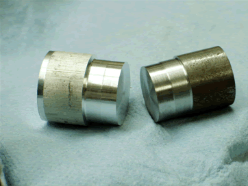
 |  |  |
This 11-year-old cobalt knife tool is one of my favorite tools. When used with a slightly negative lead angle it can take whisper thin sizing cuts off a thin work piece or give you a mirror-finished facing cut. Honed after every use and before critical cuts, it has seen the grinder only on the day it was made. Try one – you will like it!
I hope this helps you grind a good tool and enhances your enjoyment of this great hobby.
Article resource : www.machinistblog.com


Based in India, Udehra Mechanical Works is a prominent manufacturer and suppliers of huge variety of high tensile industrial fasteners like nuts and bolts which are supplied to our reputed clients.
ReplyDeleteBolt Manufacturers India
It doesn't get any smoother. Shop Lowe's assortment of sanders & polishers, including orbital finishing sanders, Stewart Santos
ReplyDeleteI thoroughly enjoyed reading about the magic of stainless steel fasteners in the blog post. They truly are remarkable in terms of corrosion resistance and durability. If you're looking for top-notch fasteners, check out my website 304 Stainless Steel Bolts. We have a fantastic selection to choose from.
ReplyDeleteI found the article on drill bits and their different types to be incredibly helpful. It's essential to choose the right drill bit for specific tasks. By the way, if you're looking for reliable fasteners, head over to my website Duplex 2507 Fasteners. We have a wide range of options available.
ReplyDeleteThe magic of stainless steel nuts and bolts is truly remarkable, as mentioned in the blog post. If you're looking for top-notch 304 Stainless Steel Foil, visit my website Sonic Steels. We offer a wide selection of stainless steel fasteners that deliver exceptional performance.
ReplyDeleteThe blog post about a well-known manufacturer and supplier of industrial flanges was insightful. It's important to work with reliable companies. By the way, if you're looking for Seamless Pipe, I recommend visiting my website Stainless Steel 17-4 ph Seamless Welded Pipes. We provide excellent quality products.
ReplyDeleteThe paper has a clear introduction, body, and conclusion and is well-structured.
ReplyDeleteZeron 100 Plate
I admire the author's capacity for clearly articulating complicated concepts, and I value how the piece skillfully uses examples from everyday life to support its arguments.
ReplyDeleteGr 8M Hex Nut - fas10
It's a good read because the author writes excitingly and is approachable.
ReplyDeleteUNS S32205 Seamless Pipe
The article is compelling since the author's enthusiasm for the subject is evident in their writing.
ReplyDeleteASTM A240 SS 309 Shim
More people will give this topic attention because of the article you've written. Keep working to spread information! Please also visit my webpage dedicated to A333 Grade 6 Pipe
ReplyDeleteThe insights you've given about grinding lathe tools on a belt sander are really helpful for those in the machining field. If precision and quality are your top priorities, I'd suggest checking out our collection of MS SS400 Sheets on our website. They could be a game-changer for your projects.
ReplyDeleteThe information you've shared about grinding lathe tools using a belt sander is both practical and informative. Your expertise is evident, and I admire your attention to detail. If precision and efficiency are important to you, I recommend checking out our collection of Duplex S31803 Pipe on our website.
ReplyDeleteThis comment has been removed by the author.
ReplyDeleteYour detailed explanation of grinding lathe tools using a belt sander is incredibly informative. Your expertise is evident, and your tips are valuable for those in the machining field. If you're interested in expanding Weld Neck Flanges, our website could be a great resource for you.
ReplyDelete