Sliding bearings have existed since the first skid-supported wheel barrow was used by primitive man. With the invention of the wheel, efficient and robust bearings became a necessity since so much force is applied to the small area of the bearing surface. Lubrication of wood bearings probably started with animal fat grease. After metals were discovered, they were soon applied to wheel bearings.
It was with the eighteenth century industrial revolution that bearings came to the forefront of engineering endeavor. Machine speeds increased dramatically and bearings were central to rotary and linear movement. In addition, accuracy and repeatability of positioning rose in emphasis. The nineteenth century advent of railroad trains sparked further development in bearing technology. Now, not only did bearings need to operate at high speed, but heat, vibration, and shock loads were greatly increased and since railroad cars were a commodity, cost was paramount. Rolling element (antifriction) bearings proliferated during this period. The introduction of the automobile further increased the volume and decreased the cost of antifriction bearings. Because an automobile is a consumer product, bearings needed to be less dependent upon maintenance and inspection.
During World War II, ball bearing factories were an important bombing target because of their pivotal role in keeping the enemies' war effort rolling. Today, bearing design continues to progress with advanced materials and new geometries enabled by computer-aided design (CAD). Computer Aided Manufacturing, such as computer numerical controlled (CNC) machining, has drastically improved the accuracy of mass produced bearings. Accurate and position-repeatable bearings, especially linear ones, have become crucial for robot implementation.
| Fluid Film Bearings |
|
|
Historically speaking, fluid film bearings were the first type of rotary bearing to appear simply because they are more simple than rolling-contact bearings. Early sliding bearings were almost certainly first made from wood after the invention of the wheel in prehistoric times, and these were lubricated with grease derived from animal fat. Metal wheel journal bearings followed. When the industrial revolution began in the eighteenth century, machine rotational speeds reached a point where lubricated metal journal bearings became hydrodynamically isolated so that there was no metal-to-metal contact. The initial discovery was certainly by accident, but soon an empirical methodology was developed followed by the science of tribology related to journal bearings.
 A Journal Bearing Has Hydrodynamic Lubricating Layer.
When a journal bearing begins rotating, there is very little lubricant between the hole and shaft at the contact point, H0, and rubbing occurs. Therefore much friction needs to be overcome when starting a hydrodynamic journal bearing. When the bearing has reached sufficient speed, the lubricant begins to wedge into the contact area and hydrodynamic lift is attained.
Various ways have been devised for keeping a journal bearing lubricated. The lubricant often cools and cleans the bearing in addition to its lubrication function. For instance, in a siphon wick lubrication arrangement, as illustrated below, gravity provides the pressure head needed to keep the lubricant flowing to the bearing surface.
|
Siphon Wick Journal Bearing Lubrication
Another method of delivering lubricant can be done by a capillary wick, as illustrated below. The necessary pressure head is developed through capillary action within the fibers of a textile wick, as with the phenomenon of a candle wick.

Capillary Wick Lubrication Method
For applications that require significantly decrease the amount of starting friction, a hydraulic lift can be introduced.

Hydraulic Lift Lubricated Journal Bearing
Hydraulic lift journal bearings have been successfully applied to slow-moving, heavy rotating masses such as those found in steel rolling and paper mills.
| Antifriction Bearings |
|
An antifriction bearing, also known as a rolling contact bearing, is justified over a journal orfluid film bearing when very little friction is needed for low differential surface speeds. Of course, the extra mechanical complexity of antifriction bearings drives up their cost when compared to similar journal bearings.
Antifriction bearings can be categorized to two different configurations: axial ball and roller bearings, as illustrated in the following two figures respectively.
| 1. | Rotary Axial Ball Bearing: |
| 
A Typical Rotary Axial Ball Bearing |
|
| 2. | Rotary Axial Roller Bearing: |
| 
A Typical Rotary Axial Roller Bearing |
|
|
| Nomenclatures of Antifriction Bearings |
|
|
Various rolling elements of antifriction bearings are illustrated in the figure below.

Rolling Elements of Antifriction Bearings
For a typical axial bearing, its nomenclatures are annotated below.
 Axial Ball Bearing Nomenclatures
|
|
| Thrust Bearings |
|
|
Thrust bearings do what their name implies: they provide load capacity axially while still rotating.
 Rotary Thrust Ball Bearing
One form of roller bearing that deserves its own section is the tapered roller bearing.
| Tapered Roller Bearings |
|
|
Tapered roller bearings are a unique subset of axial roller bearings in which the rollers are tapered rather than straight right cylindrical. The roller shape allows thrust loads to be withstood in addition to the radial loads. A familiar application for tapered roller bearings is the central hub bearings for automobile wheels. When an auto traverses a turn, the wheels mustwithstand a significant lateral force, so that tapered roller bearings are necessary.
Tapered roller bearings have an intriguing geometry. If all rolling-contact surfaces are projected out to form cones, all cone tips converge at a single point on the central axis of the bearing. This fact enabled early machine designers to have tapered bearings fabricated without CNC equipment. The following two figures show how tapered roller bearing geometry is derived. Note how it is intuitive how the full cones roll about one another.
|
|
|
| Rotary Bearing: Load/Life Calculation |
|
As we have seen, rotary antifriction bearings are manufactured in a variety of configurations. What we present here is a method for deciding upon a configuration, and then sizing a rotary antifriction bearing. First, we look at a rule of thumb for friction-limited speed of such a bearing.
Friction in rotary bearings: A rule of thumb
Friction in rotary bearings generates heat which can eventually destroy the bearing. With friction in mind, a common rule of thumb used for the allowable speed of ball and straight roller bearings is:
| ( B + D ) · n/2 < 500,000 |
|
| Where | B | = bore diameter in millimeters |
| D | = outside diameter in millimeters |
| n | = speed in rpm |
Selection of an antifriction bearing for a particular application:
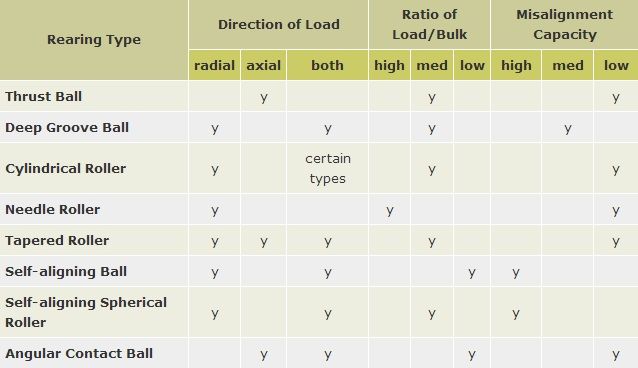
We now look at one method for selecting a rotary antifriction bearing given a load/life specification. The following table gives a qualitative overview of the characteristics of each rotary antifriction bearing type. We use this table to select the configuration of the bearing.
Now that we have decided upon the bearing type, we can move on to the more quantitative issue of sizing the bearing. Two metrics that are needed for bearing specification are the static and dynamic load capacities. Static load capacity can specify the bearing if rotational speed is slow, intermittent, and/or subject to shocks. Dynamic load capacity is used when the bearing rotational speed is smooth and relatively constant.
Static Load Specification:
The axial and radial forces acting on the stationary rotary bearing determine the Basic Static Load Rating listed in bearing catalogs. When there are both axial and radial loads on a bearing, the combined static load can be found as follows.
| Fstatic = Xsrad · Fsrad + Xsax · Fsax |
|
| If only radial forces act, |
|
| Fstatic = Fsrad |
|
| Where | Fstatic | = The combined, equivalent static bearing load |
| Fsrad | = The static radial load |
| Fsax | = The static axial load |
| Xsrad | = The static radial factor (dimensionless) |
| Xsax | = The static axial factor (dimensionless) |
|
|
The basic static load rating coefficient, Co, can be obtained from:
| Co = So · Fstatic |
|
| Where | Co | = The basic load rating |
| So | = The static safety factor (dimensionless) |
| Fstatic | = The combined, equivalent static bearing load |
|
|
Values of So depend upon the requirements for low-noise operation and the type of bearing, as shown in the following table.
Static Safety Factor (So) Guidelines
|
If the bearing is stationary for extended periods or rotates slowly and/or intermittently and is subject to shock loads, then the selection is based upon this basic load rating. Values of basic load rating, Co, for each bearing are quoted in the bearing catalogs.
Dynamic Load Specification:
The dynamic load specification of a rotary bearing is dependent on both the dynamic and static forces acting upon the bearing. Therefore, please first calculate the Static Load Specification as outlined above. Axial and radial static forces multiplied by dynamic factors combine to form the equivalent dynamic bearing load, which is calculated as follows.
| Fdyn = Xdrad · Fsrad + Xdax · Fsax |
|
| Where | Fdyn | = Equivalent dynamic bearing load |
| Fsrad | = Static radial load on bearing |
| Fsax | = static axial load on bearing |
| Xdrad | = radial dynamic factor (dimensionless) |
| Xdax | = axial dynamic factor (dimensionless) |
When Fsax = 0 or is relatively small up to Fsax/Fdyn = e (The values of Fsrad, Fsax, and e are given in the Rotary Bearing Data) then
Fdyn = Fsrad
Since we have calculated the equivalent dynamic bearing load we can now compute the bearing dynamic load rating, which is used to select the bearing. Catalog dynamic load rating values should be chosen higher than the computed value for safety.
The catalog-listed dynamic load ratings are dependent upon both the equivalent dynamic load and the required bearing life. The ISO equation for the basic rating life is:
 |
|
| Where | L = | basic rated life (millions of revolutions) |
| C = | basic dynamic load rating |
| P = | equivalent dynamic bearing load |
| m = | exponent in the life equation,
m = 3 for ball bearings
m = 3.3 for other bearings. |
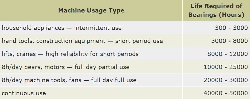
Basic Rated Life of Bearings:
The basic rated life is defined as the number of revolutions that ninety percent of a group of identical bearings would be expected to achieve. It is determined via the life required of the bearing. Typical life requirements for various machine categories are listed below.
| Linear Bearings Introduction |
|
|
Linear bearings are used primarily where something needs to be moved along a straight line with high accuracy. In other words, the object needs to only translate in one direction, and possibly move back to its starting position with high repeatability.
The implications for robotic pick-and-place are obvious, as are uses for optical test fixturing and calibration. The robotic uses of linear bearings have opened up a huge market for the devices in recent years. There is a plethora of manufacturers of the devices, so much so that standardization is sometimes a problem. The three primary types of linear bearings are ball, crossed-roller, and slide bushing.
 Common Linear Bearings
|
|
|


All the bearings are used for the anti friction purpose. But what reason for separating the anti-friction bearings?
ReplyDeleteYou have beaten yourself this time, and I appreciate you and hopping for some more informative posts in future. Thank you for sharing great information to us. ball bearings in us
ReplyDelete